
કોઈ પરિપથ ઘટકમાંથી વોલ્ટેજ અને પ્રવાહ છે:
v(t) = 628 sin(314t + 45°) V
i(t) = 10 sin(314t − 45°) A
પરિપથ ઘટક ઓળખો અને તેનું મૂલ્ય શોધો.
 જવાબ અને પગલાવાર ઉકેલ

C — પ્રેરક, 200 mH. વોલ્ટેજ +45° અને પ્રવાહ −45° પર છે, એટલે વોલ્ટેજ પ્રવાહથી 90° આગળ — આ આદર્શ પ્રેરક છે. Xₗ = 628/10 = 62.8 Ω અને L = Xₗ/ω = 62.8/314 = 0.2 H = 200 mH.
વિગતવાર ઉકેલ (મૂળ ભાષામાં)
Concept Foundation — Phase Tells You the Element
For ideal sinusoidal circuit elements, the relative phase of voltage and current is a direct fingerprint of the element. A resistor has voltage and current in phase. For an inductor, voltage leads current by 90°. For a capacitor, current leads voltage by 90°.
- Resistor: V and I are in phase.
- Inductor: V leads I by 90° (current lags voltage).
- Capacitor: I leads V by 90° (current leads voltage).
Step 1 — Compare the Given Phases
φ_V = +45°
φ_I = −45°
φ_V − φ_I = +90°
Therefore voltage is 90° ahead of current. The element must be a pure inductor . This single phase check immediately eliminates both capacitor options.
Step 2 — Find the Reactance Magnitude
The given sine-wave amplitudes are peak values. Their ratio can be used directly because dividing both by √2 to convert to RMS would cancel the same factor.
X_L = V_m/I_m = 628/10 = 62.8 Ω
Step 3 — Convert Reactance to Inductance
X_L = ωL
L = X_L/ω
L = 62.8/314 = 0.2 H
L = 200 mH
Frequency Check
ω = 2πf
f = 314/(2π) ≈ 50 Hz
The angular frequency corresponds to the familiar 50 Hz supply frequency, so the numerical scale is physically reasonable.
Phasor Figure — Use It to Lock the Concept
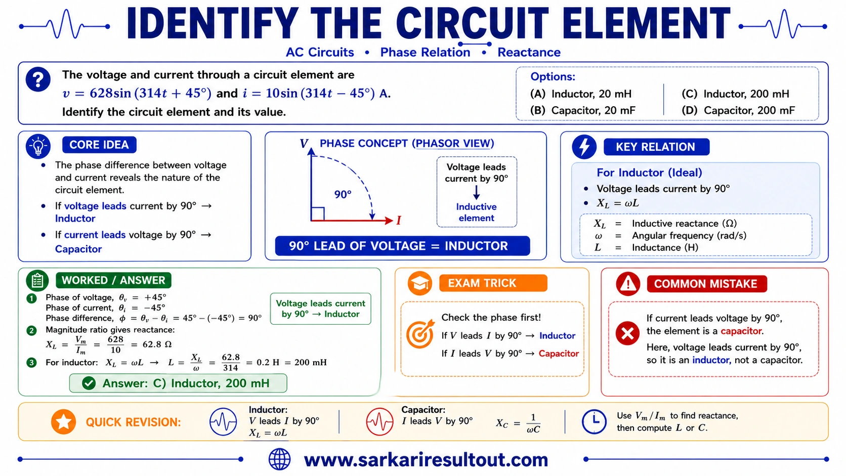
The supplied solution figure shows the phasor relation visually: V is 90° ahead of I. This is the fastest way to distinguish an inductor from a capacitor in sinusoidal steady-state questions.
Independent Verification
If L = 0.2 H and ω = 314 rad/s, then X_L = 314 × 0.2 = 62.8 Ω. With a 10 A peak current, V_m = 62.8 × 10 = 628 V, exactly matching the question.
Exam Strategy
Phase first, magnitude second. Identify L/C/R from the phase relation before calculating the component value. This avoids doing correct arithmetic for the wrong element.
Quick Trick
V leads I by 90° → inductor. Then L = (V/I)/ω = (628/10)/314 = 0.2 H = 200 mH.
Why Other Options Are Wrong
- A — Inductor, 20 mH: the element type is correct, but 20 mH would give Xₗ = 6.28 Ω, not 62.8 Ω.
- B — Capacitor, 20 mF: a capacitor would have current leading voltage, opposite to the given phase relation.
- D — Capacitor, 200 mF: also fails the phase test before any magnitude calculation is attempted.
Common Mistake
Reversing the mnemonic and choosing a capacitor, or converting only V or only I to RMS before taking the ratio.
The voltage and current through a circuit element are:
v(t) = 628 sin(314t + 45°) V
i(t) = 10 sin(314t − 45°) A
Identify the circuit element and determine its value.
Answer & step-by-step solution
The phase difference identifies the element before any calculation: voltage is at +45° and current at −45°, so voltage leads current by 90°, which is the ideal-inductor relation. Then Xₗ = 628/10 = 62.8 Ω and L = Xₗ/ω = 62.8/314 = 0.2 H = 200 mH.
Concept Foundation — Phase Tells You the Element
For ideal sinusoidal circuit elements, the relative phase of voltage and current is a direct fingerprint of the element. A resistor has voltage and current in phase. For an inductor, voltage leads current by 90°. For a capacitor, current leads voltage by 90°.
- Resistor: V and I are in phase.
- Inductor: V leads I by 90° (current lags voltage).
- Capacitor: I leads V by 90° (current leads voltage).
Step 1 — Compare the Given Phases
φ_V = +45°
φ_I = −45°
φ_V − φ_I = +90°
Therefore voltage is 90° ahead of current. The element must be a pure inductor . This single phase check immediately eliminates both capacitor options.
Step 2 — Find the Reactance Magnitude
The given sine-wave amplitudes are peak values. Their ratio can be used directly because dividing both by √2 to convert to RMS would cancel the same factor.
X_L = V_m/I_m = 628/10 = 62.8 Ω
Step 3 — Convert Reactance to Inductance
X_L = ωL
L = X_L/ω
L = 62.8/314 = 0.2 H
L = 200 mH
Frequency Check
ω = 2πf
f = 314/(2π) ≈ 50 Hz
The angular frequency corresponds to the familiar 50 Hz supply frequency, so the numerical scale is physically reasonable.
Phasor Figure — Use It to Lock the Concept
The supplied solution figure shows the phasor relation visually: V is 90° ahead of I. This is the fastest way to distinguish an inductor from a capacitor in sinusoidal steady-state questions.
Independent Verification
If L = 0.2 H and ω = 314 rad/s, then X_L = 314 × 0.2 = 62.8 Ω. With a 10 A peak current, V_m = 62.8 × 10 = 628 V, exactly matching the question.
Exam Strategy
Phase first, magnitude second. Identify L/C/R from the phase relation before calculating the component value. This avoids doing correct arithmetic for the wrong element.
Quick Trick
V leads I by 90° → inductor. Then L = (V/I)/ω = (628/10)/314 = 0.2 H = 200 mH.
Why Other Options Are Wrong
- A — Inductor, 20 mH: the element type is correct, but 20 mH would give Xₗ = 6.28 Ω, not 62.8 Ω.
- B — Capacitor, 20 mF: a capacitor would have current leading voltage, opposite to the given phase relation.
- D — Capacitor, 200 mF: also fails the phase test before any magnitude calculation is attempted.
Common Mistake
Reversing the mnemonic and choosing a capacitor, or converting only V or only I to RMS before taking the ratio.

किसी परिपथ अवयव के माध्यम से वोल्टेज और धारा हैं:
v(t) = 628 sin(314t + 45°) V
i(t) = 10 sin(314t − 45°) A
परिपथ अवयव पहचानिए और उसका मान ज्ञात कीजिए।
उत्तर और चरणबद्ध हल
C — प्रेरक, 200 mH। वोल्टेज +45° और धारा −45° पर है, यानी वोल्टेज धारा से 90° आगे — यह आदर्श प्रेरक है। Xₗ = 628/10 = 62.8 Ω और L = Xₗ/ω = 62.8/314 = 0.2 H = 200 mH।
विस्तृत हल (मूल भाषा में)
Concept Foundation — Phase Tells You the Element
For ideal sinusoidal circuit elements, the relative phase of voltage and current is a direct fingerprint of the element. A resistor has voltage and current in phase. For an inductor, voltage leads current by 90°. For a capacitor, current leads voltage by 90°.
- Resistor: V and I are in phase.
- Inductor: V leads I by 90° (current lags voltage).
- Capacitor: I leads V by 90° (current leads voltage).
Step 1 — Compare the Given Phases
φ_V = +45°
φ_I = −45°
φ_V − φ_I = +90°
Therefore voltage is 90° ahead of current. The element must be a pure inductor . This single phase check immediately eliminates both capacitor options.
Step 2 — Find the Reactance Magnitude
The given sine-wave amplitudes are peak values. Their ratio can be used directly because dividing both by √2 to convert to RMS would cancel the same factor.
X_L = V_m/I_m = 628/10 = 62.8 Ω
Step 3 — Convert Reactance to Inductance
X_L = ωL
L = X_L/ω
L = 62.8/314 = 0.2 H
L = 200 mH
Frequency Check
ω = 2πf
f = 314/(2π) ≈ 50 Hz
The angular frequency corresponds to the familiar 50 Hz supply frequency, so the numerical scale is physically reasonable.
Phasor Figure — Use It to Lock the Concept
The supplied solution figure shows the phasor relation visually: V is 90° ahead of I. This is the fastest way to distinguish an inductor from a capacitor in sinusoidal steady-state questions.
Independent Verification
If L = 0.2 H and ω = 314 rad/s, then X_L = 314 × 0.2 = 62.8 Ω. With a 10 A peak current, V_m = 62.8 × 10 = 628 V, exactly matching the question.
Exam Strategy
Phase first, magnitude second. Identify L/C/R from the phase relation before calculating the component value. This avoids doing correct arithmetic for the wrong element.
Quick Trick
V leads I by 90° → inductor. Then L = (V/I)/ω = (628/10)/314 = 0.2 H = 200 mH.
Why Other Options Are Wrong
- A — Inductor, 20 mH: the element type is correct, but 20 mH would give Xₗ = 6.28 Ω, not 62.8 Ω.
- B — Capacitor, 20 mF: a capacitor would have current leading voltage, opposite to the given phase relation.
- D — Capacitor, 200 mF: also fails the phase test before any magnitude calculation is attempted.
Common Mistake
Reversing the mnemonic and choosing a capacitor, or converting only V or only I to RMS before taking the ratio.
 More AC Circuits questions